The Arm
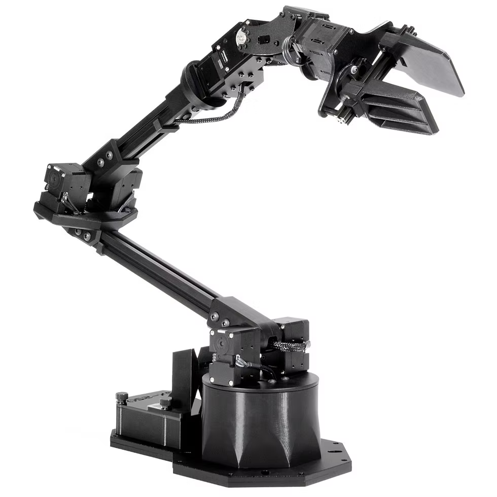
The WidowX Arm comes with open source code for its inverse kinematics, allowing for precise coordinate frame motion and correction. All code, however, must be executed in a docker container in the directory bridge_data_robot_main. For details on the computational setup, see the bridge_data_robot_main README.
The chess_bot repository was an invaluable reference for testing and debugging the WidowX arm computational setup. Several of the files regarding the computational setup were modified based on this reppository.
Using a bounded normal distribution, we enable the arm to randomize the location from which it picks up a resistor so that it approaches a slightly different spot every time. The normal distribution is more effective than a uniform distribution because the unbent resistor leads tend to force the magnetic parts of the resistor towards the center of the box.
The Camera
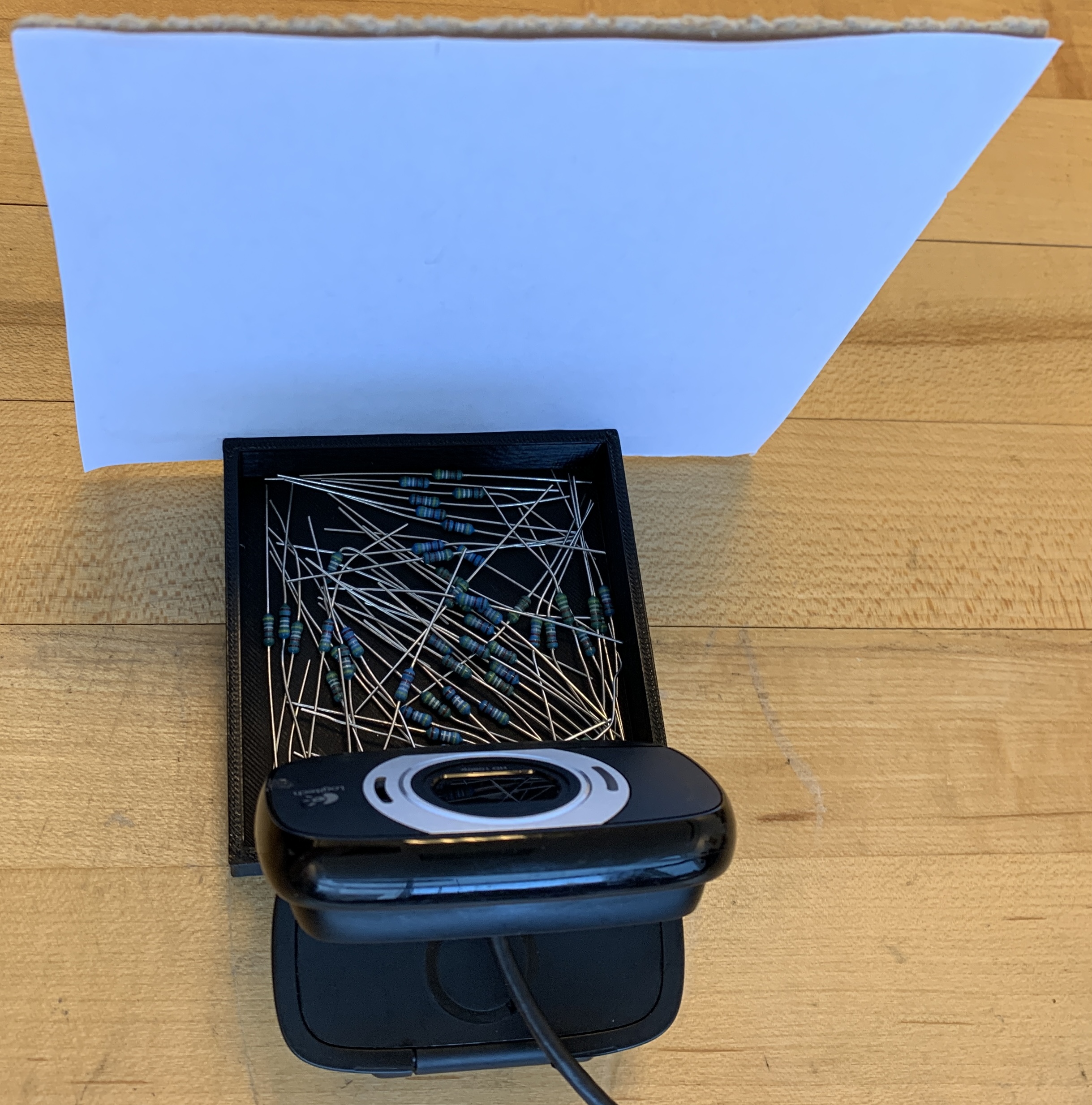
In order to ensure consistency, we 3D printed a resistor depot that we could mount the camera to and a cardboard backdrop. This is critical for the detection algorithm. The backdrop allows the algorithm to isolate the end of the magnet precisely without interfering noise and the constrained camera location ensures that the resistors are in focus and an appropriate size in the image. The .ai file is included for specifics.
Machine Vision
Counting the number of resistors in an image is challenging because they can vary in size, shape, color, and orientation. To determine whether the arm has picked up no resistors, one resistor, or more than one resistor, we implemented a binary filter and contour detection in OpenCV. The binary filter ensures the background is a completely uniform color, enabling more accurate contour detection. Using the bounds specified by each contour, we can detect the total percentage of pixels within each image that belongs to a resistor. Depending on whether this percentage exceeds a couple of thresholds, we can determine if the arm has successfully picked up a single resistor.
The Electromagnet
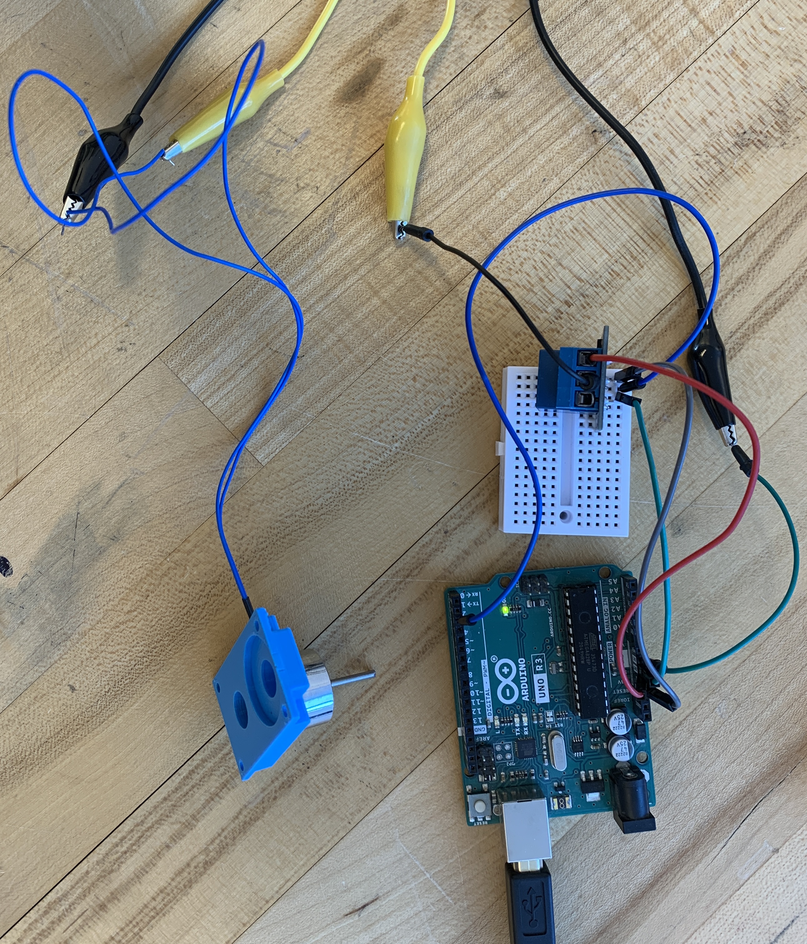
We used an Arduino Uno as a power source and controller for the electromagnet. Because the digital output pins cannot supply the required 5V to power it, the Arduino is wired to a relay that recieves power from the 5V pin and toggles on and off the magnet according to a digital signal. The magnet itself we mounted onto the arm where the gripper used to be using a 3D printed mount. See the image above for the full electrical system. Attached to it is a ~2.5mm diameter ferromagnetic steel rod to increase the precision of the magnet by concentrating the magnetic field.